Feb-17 ⋅⋅⋅
233D Transmitter Restoration Project
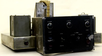
Jules, Mike Wilson, Jim Irvine and Jim Shanklin were there and I think we made some progress. I have pulled all the chassis from the RF cabinet except for the exciter and the output network. The two remaining assemblies are ready to pull, but there isn’t much bench space available, so I chose to leave them in place until we find more space. It would be really great if we could find some roll around shelving to store the chassis after they are cleaned. We could also use some sort of cart to transport the chassis to our vehicles when we want to take them out for work. I know the carts have always been difficult to find, but maybe someone knows how to find one. The telco relay chassis looks a lot simpler than I had expected. Dirty and the contacts will need liberal application of deoxit. Good news is that the wiring appears to be in really good condition. The wiring appears to be in better condition throughout the transmitter than I had thought. There may be some isolated areas where high heat caused insulation cracking, but generally, no problems. Major concerns at this point is finding ways to protect the harness during the cabinet repair/cleanup/repaint. Not much progress on repair/paint process. Bill Carns from the CCA is expected to be here around February 16 and he expects to provide suggestions on over-spray of the St. James Gray paint. He has restored a number of Collins products that use that paint, so I hope he can help. I called Klinger and they referred me to someone in Marion who does not appear to be available, so we need to keep looking. I have the Klinger “factory” contact info and there is a gentleman there who was involved with most of the Collins coatings, but he was not in when I called. Someone in CA has spray cans available for around $15, so that could be better than getting Klinger to make a special run. (unless Klinger is interested in making a “donation” to the project! Sure would to keep it local, if we can.) At this point, I suggest we wait for Bill’s inputs. Rod found a 231D-20 manual with Autotune shaft CPNs penciled in. Looking yesterday indicates that the shaft appears to be 1/4” shaft with flats for the screws to keep from turning. Hopefully, someone can find some of the coupling drawings in PDM so we can get them to Don Grimm so he can machine replacements. Mike Wilson will check at RCRV meeting today to see if we can get 10 minutes or so on the agenda next Thursday to get the project setup as a project for that group. Plan is to attempt to recruit some additional help from that group. I’ll put together a Powerpoint for that meeting need some of the jpegs that were on the eBay site. Looked at the site this morning and only one image is still available and I couldn’t get it copied anyway. Lawrence: I recall you said you had the images available. Could use them before next week. I am creating a system drawing on a 24 inch by 8 foot paper that should serve as a troubleshooting tool and help understand how the system works. Most of the RF bay and modulator bay interconnect is complete except for function labeling. Will attempt to get it done by next Wednesday. I am planning to maintain the Wednesday sessions during the museum opening schedule: 11:30 to 1. I plan to be there a couple of other days during the week, but have to work it in with other projects. Mike has provided some good suggestions with regard to organizing the project. I certainly appreciate all the help I can get in that regard. Any other suggestions appreciated. Jim |
||
| February 17, 2013 |
