Mar-19 ⋅⋅⋅
233D Transmitter Restoration Project
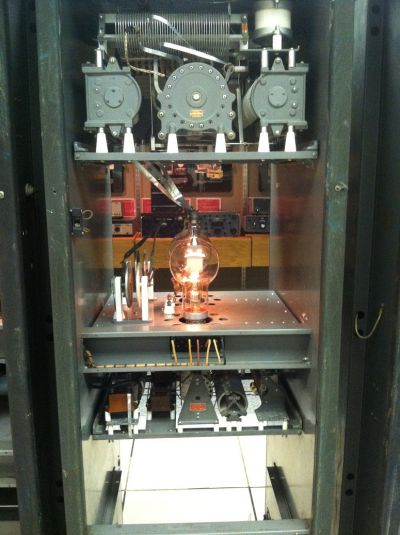
Mike will install the control cable between the power bay and the power contactor so we can check out the big plate transformer contactors. We’ll have to defeat the door interlocks to make this work, but they absolutely have to be enabled before we apply any high voltage from the plate transformer. In spite of the fact that I labeled all the wires in the HV rectifier chassis before it went to re-plating last year (and took pictures), one of the wires was apparently labeled in error. The wiring is fairly simple, but since high voltage is involved, I need to make sure I get it right. I want to get the chassis reinstalled so we can “cook” the 872A (Mercury Vapor rectifier tubes) and hopefully heat up the potting material in the transformer enough to get the top cover back on. Long story; stop by if you’re interested and I tell you the sordid story. (Mike edit: I’m going to get a bigger clamp and a heat gun and try to get the lids back on without having to rely on the transformer getting warm enough to soften up the potting material). The wirewound power resistors in the high voltage supply bleeder network are still a problem; but it turns out that the old Allen Bradley division of Rockwell Automation operated Milwaukee Resistor that specialized in those resistors. The Dale division of Vishay has current data sheet for those parts so now it is just a matter of finding stock on what we need and finding out what the ransom will be on those big beauties. Jim |
|
| March 20, 2014 |