A.A. Collins:
Amateur Radio:
1926 Radio Age •••
- Receiver Article
|
April 1926 Radio Age Article
| RADIO AGE for April, 1926 |
The Magazine of the Hour 33 |
 |
Getting Acquainted With
the Short Waves
BY ARTHUR A. COLLINS |
| (Radio 9CXX) |
|
THERE seems to be a growing interest among radio enthusiasts, who have more than a casual interest in the technical end of the game, in the remarkable development of the shorter wavelengths which has taken place within the last year or so, and for which that class of experimenters known as radio "amateurs" is largely responsible.
Many broadcast listeners enjoy nightly programs that have been sent half-way across the continent on wavelengths between 60 and 40 meters and rebroadcast by stations on the broadcast band of wavelengths.
Many of these people would be surprised to know of the numerous other activities on these frequencies which are commonly called the "short" wavelengths, i.e., from 90 to 15 meters.
A receiver for these wavelengths is the first requisite for getting acquainted with them.
Although the design of such a receiver offers little difficulty to the older members of the radio fraternity, a little information as to the principles of design and constructional data should be welcomed by radio fans who are just entering the amateur game.
The Receiver
AMATEURS have found that receivers with several steps of tuned radio frequency amplification, which are so popular for broadcast reception, are somewhat impractical on the shorter wavelengths, and have almost universally adopted some modification of the less complex "three circuit regenerative."
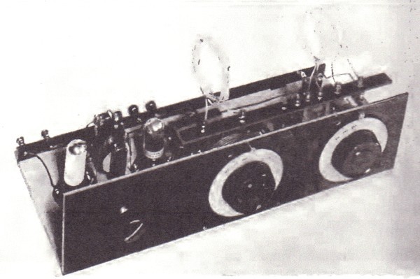
The receiver at my station, 9CXX, is constructed in the following manner.
Two well built "low-loss" condensers, one 150 mmfd. with logarithmic plates for the grid
|
circuit, and one 250 mmfd. for the plate circuit, are mounted on a small hard-rubber panel and provided with large vernier dials.
The 150 mmfd. condenser occupies the right-hand position, since this condenser is used in frequency variation, whereas the larger condenser is merely a regeneration control.
The panel is mounted on a wooden base-board provided with binding-posts for battery connections, and a hard-rubber strip half an inch wide and extending the full length of the panel is mounted on the back of the panel near the upper edge by means of two small brass angles.
On this strip are mounted the binding-posts for connecting the coils.
Winding Data
COILS are space-wound of No. 14 DCC magnet wire.
The turns are formed by winding them around some cylindrical object 2½ to 3 inches in diameter (e.g. a wooden rolling-pin), removed, and the required number of turns clipped off, leaving sufficient surplus for the leads to the binding-posts.
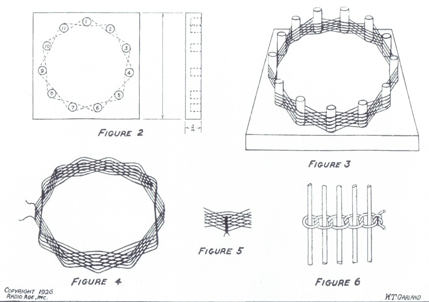
The turns are spaced by tying them with large cotton twine as shown in Figures 5 and 6. The coils are so tied at four or five points on the circumference of the coil, and a few drops of collodion applied to the twine only, for the sake of mechanical rigidity.
The leads will be stiff enough to support the coils from the binding-posts.
The following coil sizes will be found suitable in most cases: antenna coil 5 turns, plate coil 3 turns, and grid coil 16 turns for 80, 8 turns for 40, and 4 turns for the 20 meter bands.
For the sake of interchangeability, be sure to wind all coils in the same direction.
|
A UV 199 Radiotron is perhaps the best detector for high frequencies because of its low internal capacity and low current consumption.
The tube should be placed in an inverted position and the connections soldered directly to the studs on the tube base.
Incidentally, care should be taken to solder to the right studs, since a mistake may be expensive.
The grid condenser and leak used with the detector should be of the very best quality, since quietness and ease of operation depend in a large measure upon these two items.
A 250 mmfd. condenser and a 5 megohm leak are well adapted for use with a UV199 tube.
Short R.F. Leads
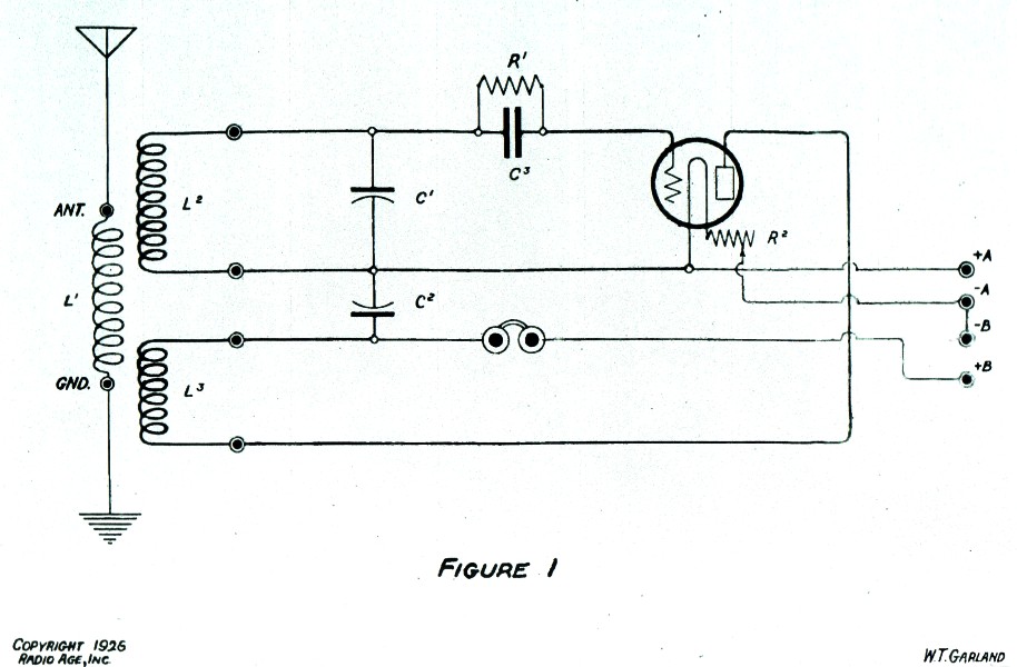
SCHEMATICALLY the circuit is shown in Figure 1. By exercising his ingenuity, the builder can assemble the parts and wire the set so that none of the radio frequency leads (shown by heavy lines in the diagram), need exceed three inches in length.
A one step amplifier may be added in the usual manner, or the output leads may be connected to the input terminals of the first transformer of your broadcast receiver, thus the same amplifier can be utilized for both sets.
The reader will no doubt be impressed by the simplicity of this equipment and by the ease with which it may be constructed. Simplicity and efficiency go hand in hand on the short wavelengths.
As mentioned before, the variable grid condenser is used for station selection, and the plate condenser accomplishes regeneration control.
The entire range from approximately 95 to 12 meters is covered by substituting the different grid coils.
It will be found that the ranges of the individual coils overlap somewhat, so that every part of the band is accessible.
|
| 34 RADIO AGE for April, 1926 |
The Magazine of the Hour |
|
Practically all communication on the short wavelengths is carried on in Continental telegraph code.
If the reader is unacquainted with this code, he should be able to learn to copy it at a reasonable rate in a few weeks by applying himself diligently to practice with a hand key and test buzzer, and to listening to the many stations operating on the high frequencies.
Amateur Bands
OUR government has assigned the following bands of wavelengths to amateurs: 150-200, 75-85.7, 37.5-42.8, 18.7-21.4, 4.69-5.35, and .7477-.7496 meters.
The five meter, and 74 centimeter bands are still more or less in the laboratory stage of development, but the 20, 40, and 80 meter bands are in daily use by hundreds of amateurs who maintain contact with foreign amateurs in practically every part of the globe - a feat which would be utterly impossible on higher wavelengths with the low inputs in vogue among amateurs.
Perhaps the most international "DX" work is carried on near the 40 meter band.
European amateurs are to be found nightly in the neighborhood of 45 meters, whereas the South American "hams" take their evening siestas around 36 meters.
Our Australian brethren infest these same wavelengths in the early hours of the morning.
The question naturally arises: "Why are these high frequencies so much more effective than the lower ones?"
The "Heaviside" theory of short wave propagation is quite generally accepted as an explanation of this phenomenon.
|
The theory in its commonly accepted form is outlined briefly as follows: Physicists tell us that the actions of the sun's rays on the strata of highly rarefied gases bounding the earth's atmosphere cause the gas molecules to be ionized, forming a conducting layer varying in altitude with the intensity of the sun's rays.
It has also been found that short radio waves show a marked tendency, increasing with their frequency, to travel less along the earth's surface and to shoot out at a tangent, only to be reflected back again by this ionized layer.
From this it can be seen that a short radio wave which has traveled to this hypothetical layer and back again, would have traversed a path
of very low resistance and absorption, so that a comparatively large amount of the energy leaving the transmitter in the direction of the receiver would arrive at its destination irrespective of the distance traversed.
This effect is somewhat noticeable on 80 meters, is very pronounced on 40 meters, and is so unusual on the 20 meter band that the earth-wave is entirely absorbed within a very few miles of the transmitter and there is actually a skipped distance where no signals are received until the point is reached where the reflected wave returns to earth.
This skipped distance is commonly 300 to 1,000 miles on 20 meters in daytime, varying with the wavelength, the time of day, the season, and the latitude of the receiver and transmitter.
Short wave signals, especially those below 40 meters are remarkably adaptable for daylight communication between distant points.
|
Complications such as double-reflection and wave polarization are frequently encountered in this connection.
Research Field
THE foregoing discussion is not presented as anything new or in the least unknown to the older members of the radio game, but as something which may be of interest to the more recently knighted fans, who may desire to gain a contact with the astounding developments which have taken place in the last year or two.
A short wave receiver and a desire for information may bring you in touch with a field of research that will produce facilities of communication even more inconceivable than the present.
In the event the builder does not care to wind the coils on a solid form and space them, he may adopt the expedient shown in Figures 2, 3 and 4 in which the coils are wound on a form made up of 11 dowel pins, using the "over one and under one" winding.
The manner of tying the knots on the turns is shown in Figure 6, and again in Figure 5.
The No. 14 DCC wire is used on account of its rigidity which is highly desirable in short wave work where even a slight deviation in the spacing of turns (such as shaking), will prevent camping on a received wave's signal.
Readers interested in the short wave theory might find considerable infor-
mation in the article, on Page 13 of the February issue of Radio Age, written by Dr. E.F.W. Alexanderson; also his comments in this issue of Radio Age on "Horizontal reception of Broadcast Waves."
|
|
|