Jan-30 ĘĘĘ
233D Transmitter Restoration Project
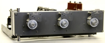
Jules expressed an interest in seeing the detail in the Autotune Maintenance section of the manual, so we might want to have it out for him to look at. I did copy most of the pages, so I will scan them and put them in the radio file. Only concern I have is the lengths of the two upper shafts may be a little different than in our transmitter, but if we can find the drawings in PDM, that should give us some good guidelines. Jules says the channel decoding is likely done in the Telco Relay assembly; appears they all drive to what I assume would be a ŌĆ£homeŌĆØ position and then reverse to the selected channel. Rod noticed there were numbers marked on the Autotune heads on the grid chassis. We expect that may have been the reason the shaft was disconnected. We expect in the later days, the transmitter was manually set to a channel by turning each head to the correct position. Hopefully, that doesnŌĆÖt mean that the Autotune system had problems. Might be worthwhile to build a cable to connect the tone control chassis from the modulator to the Telco relay chassis in the RF bay and hook up the Autotune motor. Jim |
||
| January 30, 2013 |