Apr-11 ÀÀÀ
233D Transmitter Restoration Project
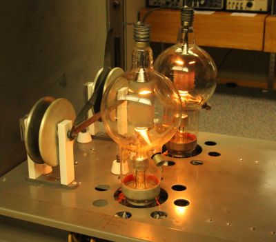
| Filament lighting went well; no smoke or sparks! | ||
I wired up the Power control chassis this morning and got must of it checked out. Indicator lights were all missing, but Menards had them, so we now have green and red lights on the panel. The big 3 pole filament relay makes lots of noise and the rubber isolators all need replacing, but it appears to work. CouldnÔÇÖt tell if the Time Delay relay was working, but the contacts are in series with the door interlock switches, so I need to simulate that to make sure. Some cosmetic work (front panel St James gray has some missing sections) and relay contacts need cleaned, but it appears to be working. Pulled up quite a bit of the floor clear to the North wall, but havenÔÇÖt found any three phase circuits that I can identify. The 208 circuit that we are using runs to the North wall in flexible conduit and then goes into a raceway that runs along the North wall. I can see two large conduits that go into the North wall that are likely the feed from the distribution panel. There is a bundle of wires that run along the raceway towards the front of the room that may have the three phase circuits. That raceway goes under the ÔÇ£ITÔÇØ skids in the NorthWest Corner of the room, so there may be a termination there that we can use. Larry said there wasnÔÇÖt much in the boxes in the skid, so maybe we can clear that space. I have pigtails that allow connection to the pins on the individual chassis, so we can continue to test the assemblies without the three phase, but we will need it to check the Autotune motor/system. Larry suggested that we try to get a three phase supply from test equipment. If we could a 1KVA supply, I expect that we would be able to test most of the system except the plate transformer. I had hoped that we would be able to run the exciter on single phase, but it appears that the plate voltage for that unit comes from the three phase plate supply. Next project is checking out the HV rectifier chassis. That will make sure the two big 872A filament transformer are working and then we can tear it down and get it ready for replating. We can reinstall the chassis in the RF bay with Autotune and have them ready for Don Grimm to come in and see what he has to do to fab the replacement shaft(s). I am still struggling with the Western Airlines drawings. I have found a couple of obvious errors that add to the confusion, but I think we can work around them. The big problem is that the drawings were apparently created for the four bay version that included both CW and Phone RF bays. WeÔÇÖll just need to do continuity checks around the system to make sure we know how circuits are routed. I have some pins that fit in the rack connectors, so it is fairly easy to check the wiring. But it takes quite a lot of time. Deferring most of the cosmetic work until later. Important that we isolate defective parts early and then we can make things shine later! Jim |
||
| April 11, 2013 |